
Introduction
Wire formers and tooling turn straight or coiled wire into repeatable parts: fasteners, springs, clips, hooks, pins, and specialty formed components. The machine bends, feeds, and cuts. The tooling determines whether the finished part actually matches the print.
Many buyers struggle with the same purchasing problem. They need equipment and tooling that match the wire material, diameter, geometry, tolerance, and production volume, plus whatever secondary operations the part requires.
Get that match wrong, and you're looking at scrapped first-run parts, tooling that wears out early, or a machine that can't hold tolerance once volume ramps up.
This guide covers industrial wire formers, the dies and punches that shape the wire, and the cutting and heading tools behind them. It also walks through selection criteria, process controls, and when custom tooling beats off-the-shelf components.
Key Takeaways
- Wire formers bend, coil, cut, draw, head, or swage wire into specified geometries.
- CNC formers fit complex or changing parts; fourslide, pneumatic, and dedicated systems fit stable runs.
- Dies, punches, guides, cutters, and feed tools matter as much as the machine.
- Tool steel choice, lubrication, and setup discipline drive consistency and tooling life.
What Are Wire Formers and Tools?
An industrial wire former is production equipment, not a hand tool. A hobby plier or hand-held bending jig relies entirely on operator skill and gets you one bend at a time. A wire former controls feed rate, bend angle, and cutoff position through mechanical, pneumatic, hydraulic, or programmed motion, producing the same part hundreds or thousands of times over.

Wire-forming equipment typically performs:
- Straightening and feeding the raw wire
- Bending into two- or three-dimensional shapes
- Coiling for springs and similar geometries
- Cutting or shearing to length
- Heading, swaging, piercing, threading, and end forming
The machine and the tooling do different jobs. The former supplies controlled movement and force. The dies, punches, mandrels, guides, rolls, and cutters actually determine the part's shape, radius, and finished features. A powerful machine with worn or mismatched tooling still produces bad parts.
Matching Equipment to the Job at Hand
Wire-forming equipment covers everything from a one-off prototype to a 100,000-piece production run. Match the machine to the job:
- Manual bender — enough to prove out a design concept
- CNC former — best when part numbers change often
- Dedicated multislide — earns its keep on long, stable runs where repeatability beats changeover speed
Choose based on part complexity, required repeatability, and the volume you actually plan to produce.
Types of Wire Formers and Wire-Forming Tools
Forming Machine Categories
Wire-forming machines differ in motion, flexibility, and setup time:
- Manual and semi-automatic formers — best for prototypes, repairs, low-volume parts, and simple bends where operator involvement is fine.
- CNC wire-forming machines — feed, straighten, bend, and cut to programmed dimensions; strong fit for frequent design changes and low-to-medium volumes, with operations limited by installed tooling.
- Fourslide or multislide machines — multiple slides approach a center mandrel from different directions, coordinating feed, cutoff, and dedicated tools for complex repeatable forms. Extra stations can add more forming actions.
- Pneumatic and hydraulic forming systems — deliver controlled force for repetitive or heavier-gauge work, often as subsystems inside a larger machine rather than a standalone class.
Supporting Tools That Control Wire Geometry
Forming machines only hold geometry when paired with the right supporting tools:
- Feed and prep: straightening rollers, feed rolls, guides, collets, and wire-drawing dies
- Shape control: forming pins, mandrels, rotary tools, bending dies, and radius tools
- Cut and finish: cut-off blades, shear tools, chamfering tools, and end-finishing components
Quality FORM Tools builds to that same sequence—dies, punches, cut-offs, quills, feed rolls, and wire draw dies—so each station gets a matched tool instead of a one-machine catch-all.
Specialized Tooling Operations
Some parts need more than a bend and a cut:
- Heading and upsetting tools form a head on the wire end—standard in fastener production.
- Swaging and extrusion tooling reduces, enlarges, or reshapes wire ends.
- Piercing, slotting, threading, and custom-hole tooling add attachment or retention features.
Standard vs. Custom Tooling
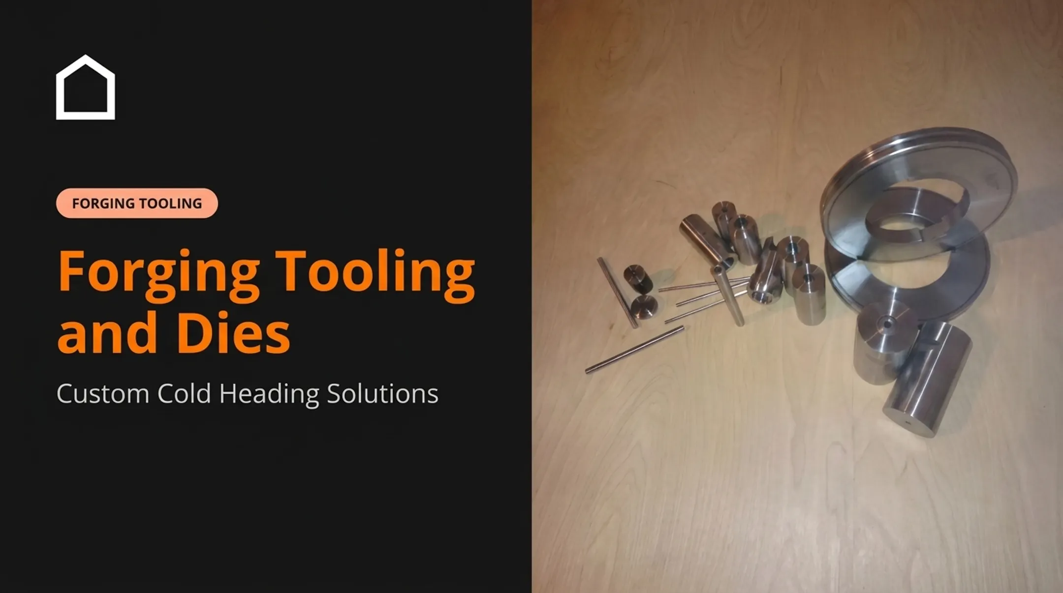
Off-the-shelf tooling works when your part matches a common wire size and geometry. A custom tool becomes necessary when the part print, machine model, material spec, or production requirement doesn't line up with anything stocked. Complete cold heading tooling packages, built and matched as a set, cut fit-up issues that show up when components are sourced one piece at a time.
How to Choose the Right Wire Former and Tooling
Start With the Part Specification
Before you shop for equipment, document:
- Wire material, diameter or cross-section, tensile strength, and hardness
- Bend radii, leg lengths, pitch, angles, end conditions, and critical dimensions
- Part type: 2D, 3D, coiled, threaded, headed, pierced, or mixed secondary operations
Match Equipment to Production Requirements
Map the job against your real production profile:
- Prototype and short-run demand
- Recurring volume and batch size
- Changeover frequency
- Available operator skill
Flexible CNC equipment fits varied part numbers and frequent changeovers. Dedicated tooling fits stable, repeatable production when the design is locked.

Verify Tooling and Machine Compatibility
Confirm dies, punches, guides, cutters, feed systems, and mandrels actually fit your former and wire size. Ask suppliers about:
- Setup documentation
- Tool-life expectations
- Spare component availability
- Maintenance requirements
- Support for future design revisions
Choose Tool Materials Based on the Application
Once the machine and tooling package fit, steel grade drives wear resistance, chipping risk, and service life:
| Tool Steel/Material | Typical Role | Trade-off to Consider |
|---|---|---|
| D2 (cold-work) | Punches, dies, cutting tools | High wear resistance but only moderate toughness, per Uddeholm's D2 data sheet |
| S5 (shock-resisting) | Punches exposed to impact | Better impact resistance; check abrasive wear exposure too |
| H13 (hot-work) | Forging dies primarily | Not the automatic default for ordinary cold wire bending |
| M2 (high-speed steel) | Cutting edges, recess punches | Good edge retention under repeated cycling |
| Carbide | Heading dies for screws, bolts, rivets | Excellent wear resistance; more prone to fracture than a tougher steel under impact |
Quality FORM Tools works with M2, D2, H13, and S5 for custom wire form tooling, cold header recess punches, and complete tooling packages—matching grade to the print and forming load instead of defaulting to one steel.
Build Your RFQ Checklist
With machine fit and material choice defined, send suppliers:
- Drawings or CAD files
- Wire specifications
- Annual or batch quantities
- Tolerances and inspection requirements
- Machine make and model
- Existing tooling details
- Delivery expectations
State whether you need a full tooling progression, a replacement punch or die, a prototype tool, or production-volume tooling. That scope call usually drives lead time and cost more than any other RFQ detail.
Wire-Forming Process, Materials, and Quality Considerations
Typical Production Sequence
- Review the drawing and material specification to confirm dimensions, tolerances, and wire grade before setup
- Prepare the wire and set up straightening and feeding components so stock enters the former clean and consistent
- Program or adjust the former and install forming tools matched to the bend sequence and wire diameter
- Run first-piece samples and correct for springback or dimensional variation before releasing the job
- Add secondary operations (cutting, heading, swaging, piercing, threading, coating, or heat treatment) only as the print requires

Material Selection Effects
Different wire materials behave differently under forming force:
- Carbon and alloy steel – ASTM A510/A510M covers general requirements; specify grade and condition before setting tooling parameters.
- Stainless steel – temper and cold-work condition matter more than the "stainless" label alone. Don't reuse a setup across grades just because both are stainless.
- Aluminum – bend behavior depends on alloy and temper, not just diameter.
- Copper and brass – alpha brass cold-works readily; higher second-phase content changes forming behavior. Verify alloy and temper rather than assuming.
- Specialty alloys (chromium-nickel steels, etc.) – qualify with trial runs rather than assuming a universal tooling load or cycle rate.
Springback correction is part- and lot-specific. Validate bend geometry on the actual wire lot you're running, not just the spec sheet.
Quality Control and Maintenance
Watch for these failure points on every run:
- Wire diameter variation and inconsistent straightness
- Tool wear, burrs, cracks, and surface damage
- Incorrect bend location or angle
- Springback and cumulative dimensional error
Control them with first-article inspection, in-process checks, final dimensional inspection, and functional testing when the application demands it.
Keep the process stable between jobs:
- Clean and lubricate tooling on a schedule matched to the machine
- Check alignment and inspect for wear regularly
- Replace damaged components before they affect the next run
- Record setup parameters so repeat jobs don't require re-solving the same problem
Preventive maintenance protects repeatability and cuts unplanned downtime. Gains depend on your equipment and part mix, not a fixed percentage.
Conclusion
A wire former is only one piece of the system. Dies, punches, feed components, cutters, guides, material selection, and inspection practices all shape the finished part just as much as the machine itself.
When evaluating a new job, weigh these factors together—not one at a time:
- Part geometry and wire specification
- Tolerances and production volume
- Machine compatibility and tooling material
- Ongoing maintenance needs
If you're tooling up a new part number, replacing a worn punch or die, or working through a custom forming challenge, send a print and production details to a qualified tooling supplier.
Quality FORM Tools reviews specialty wire-form, cold-header, stamping, forging, and replacement tooling from its Hammond, Indiana shop. The team can advise on tool steel selection, tooling packages, and setup documentation before you commit to a production run.
Frequently Asked Questions
What tools are used for wire forming?
CNC or manual formers, dies, punches, mandrels, straightening rollers, feed rolls, cutters, guides, swaging tools, and inspection equipment all play a role, depending on the part's complexity.
What is a wire former?
A wire former is equipment that reshapes supplied wire through controlled feeding, bending, coiling, cutting, heading, or related operations to produce a specified part geometry repeatedly.
What is the difference between a wire former and a wire bender?
Wire bending is a single operation. A wire former may integrate bending with feeding, cutting, coiling, heading, swaging, or piercing in one coordinated process.
Which wire-forming machine is best for production?
Match the machine to your geometry, wire size, tolerance, changeover frequency, and volume. CNC, fourslide, hydraulic, pneumatic, and dedicated systems each serve a different production profile.
How do I choose tooling for a wire-forming application?
Evaluate the part print, wire material and diameter, bend radii, forming forces, machine compatibility, tool steel, expected production volume, and inspection requirements before ordering.
Can wire-forming tools be customized?
Yes. Custom dies, punches, recess tools, guides, cutters, and complete tooling packages can be built around a specific part print, machine, material, and production requirement.