
Introduction
Every stamped bracket, drawn housing, or pierced panel on a production line started as a flat sheet and a die built to shape it the same way, thousands of times over. For US manufacturers, that repeatability is the business case for stamping over slower, less consistent processes.
Many production teams run into premature tool wear, inconsistent burrs, or parts that drift out of tolerance mid-run. Often, the root cause traces back to tooling specified from a part sketch alone, without full documentation of material, press capability, and expected volume.
Choosing the right die means weighing part geometry, material and thickness, tolerances, production volume, press tonnage, tooling life, and maintenance needs together. This guide defines what a forming die actually is, compares the die types and processes you're likely to specify, and walks through how to match tooling to a real production job.
Key Takeaways
- Sheet metal dies cut or form stock with punches, cavities, holders, guides, and ejectors in a press.
- Die selection depends on the operation, part geometry, material behavior, and volume, not part shape alone.
- Correct clearance, radii, and alignment reduce defects and extend tool life.
- Full part documentation and press specs should drive tooling selection, not a quick sketch.
What Are Sheet Metal Forming Dies and Tooling?
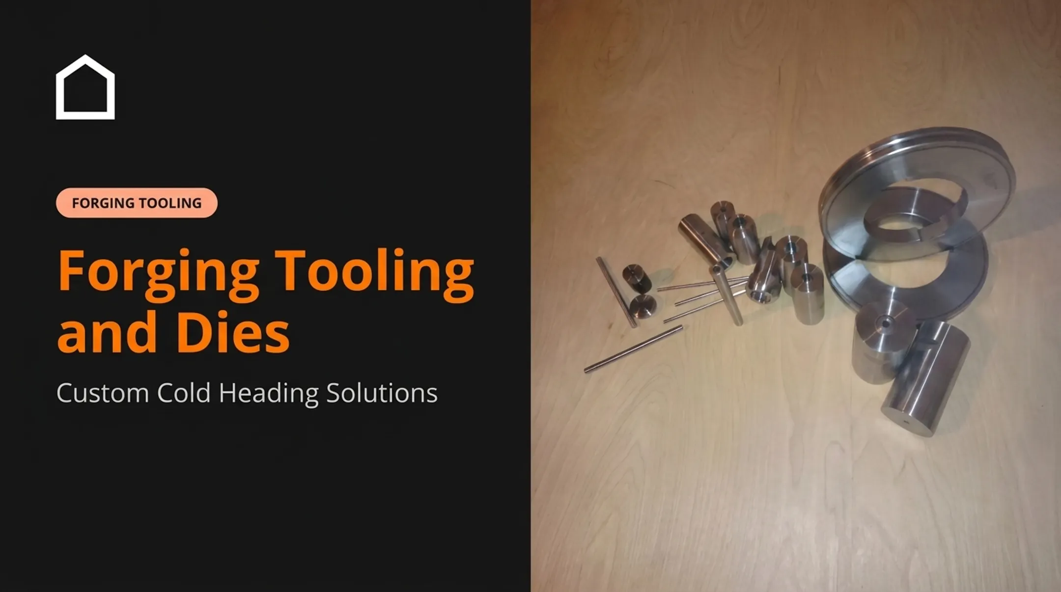
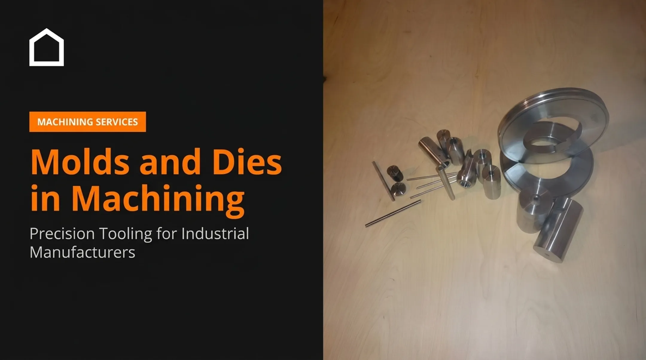
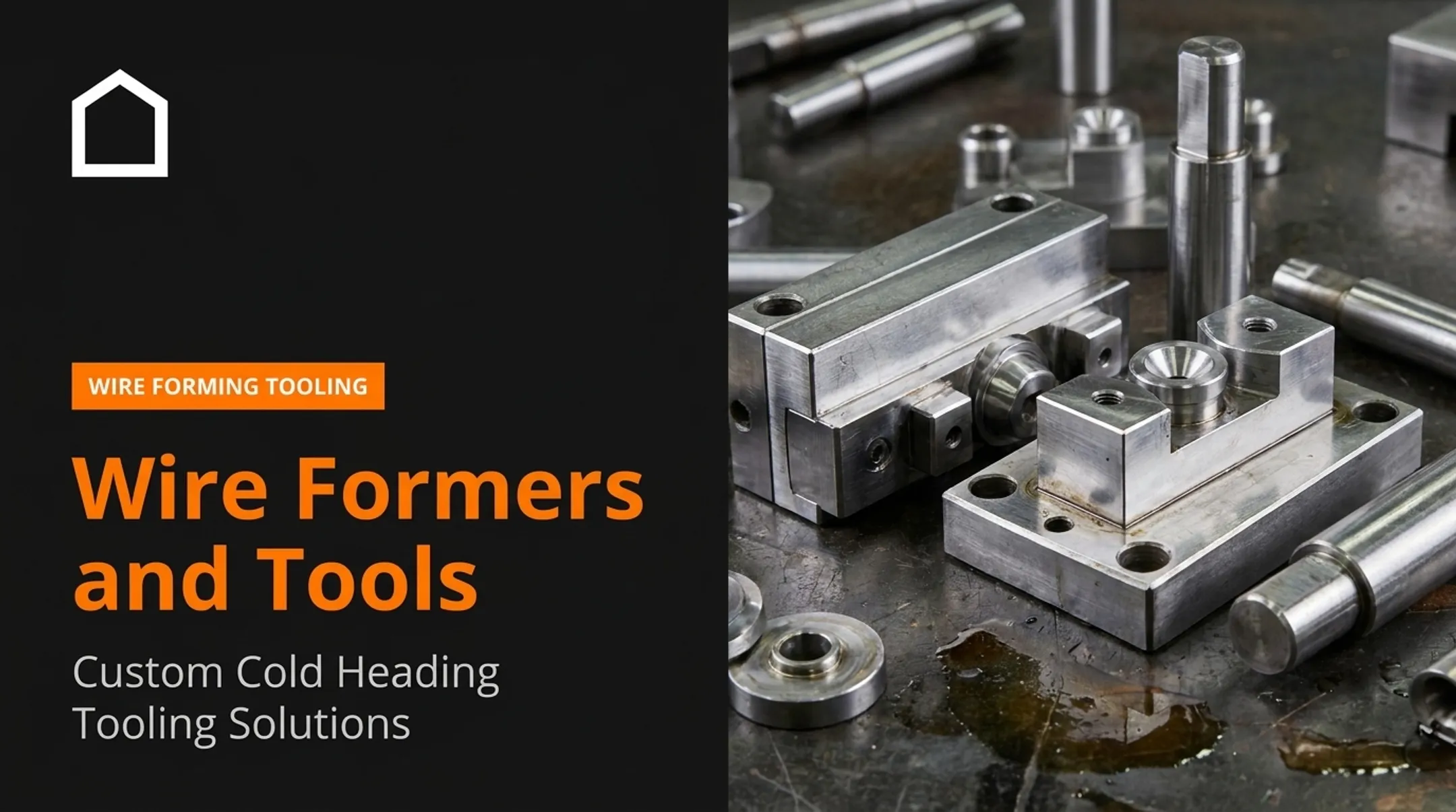
A die is a purpose-built tool set that cuts, shapes, or controls sheet metal as it passes through a press. The die (or cavity) is typically the stationary half; the punch is the moving component that engages it. "Tooling" is the broader term: it covers the complete die set plus everything supporting it.
How the Press Cycle Actually Works
The sequence is straightforward on paper: sheet or strip is positioned, the press applies force, and the punch moves relative to the die. The material is either sheared or plastically formed into the required geometry. The complexity lives in the details: clearance, alignment, and material behavior all have to line up for that sequence to produce a good part every single stroke.
Components That Make a Die Work
| Component | What it does |
|---|---|
| Die shoe | Foundation plate that carries the working components |
| Guide posts and bushings | Keep the upper and lower shoes aligned through the stroke |
| Blank holder | Restrains the blank's edge and controls metal flow into a drawing cavity |
| Stripper | Separates sheet or strip from the punch on withdrawal |
| Pressure pads and springs | Apply controlled force to hold or eject material |
| Pilots | Locate the strip precisely at each station |
| Ejector/knockout | Pushes the finished piece out of the cavity |
Cutting Dies vs. Forming Dies
Blanking and piercing are cutting operations: they shear material apart. Bending, drawing, embossing, and flanging are forming operations: they change the material's shape without separating it. Most stamped parts need both, in sequence.
Die design has to account for:
- Material thickness, strength, ductility, and grain direction
- Expected springback and surface finish
- Press tonnage and intended production rate
Skip any one of those, and you're specifying tooling for a part that doesn't actually exist on your press.
Common Types of Sheet Metal Dies
A single project often runs through several die types before the part is finished. Classification usually comes down to operation, construction, and production method.
Single-Operation and Cutting Dies
- Blanking dies cut the external part profile from sheet or strip; the blank itself is the useful piece.
- Piercing dies create holes or internal openings; the removed slug is typically scrap.
- Compound dies blank and pierce in one stroke at a single station. Best for simple flat parts such as washers, discs, and shims.
Forming and Detail Dies
- Bending/forming dies create angles, channels, curves, and tabs without cutting the material.
- Embossing dies produce shallow raised or recessed features through local stretching.
- Coining dies apply high pressure for sharply defined features, sometimes reducing local thickness.
- Flanging, restrike, and ironing dies handle edge formation, springback correction, and wall-thickness control. These steps usually follow a primary forming operation.
Progressive, Transfer, and Deep-Drawing Dies
- Progressive dies run a strip through multiple stations while a carrier keeps it attached. Ideal for repeatable, multi-feature parts at higher volumes.
- Transfer dies move separated blanks between stations, giving larger or deeper parts more room between operations.
- Deep-drawing dies use a punch, cavity, and blank holder to pull flat sheet into a hollow or cup-shaped part. Material flow is controlled to avoid tearing or wrinkling.
Prototype and Low-Volume Tooling
Additively manufactured dies can validate design and fit before committing to steel. In one documented case, Stratasys reports that printed carbon-fiber-reinforced nylon tooling formed 14-gauge carbon-steel brackets at 0.8 tons for 40 cycles without degradation. That figure is a useful data point, but it is a single vendor trial, not a universal life rating.

Polymer tooling carries different load, wear, heat, and dimensional-stability limits than hardened steel. Match prototype expectations to press force, cycle count, and surface requirements before you commit.
Common Sheet Metal Forming Processes
Forming works through controlled tension, compression, or a mix of both. Defects show up when material flow exceeds either the material's formability or the die's ability to control it.
Cutting and Basic Shaping
Blanking, piercing, shearing, trimming, and notching all depend on coordinating punch-to-die clearance with material type and thickness. Get the clearance wrong, and you'll see excessive burrs, premature wear, or torn edges.
Bending methods vary by application:
- V-bending — a ram presses sheet over a V-shaped die opening
- Wipe bending — a pressure pad holds the sheet while a punch wipes it against a die edge
- Rotary bending — a rotating tool forms the bend with less scuffing on finished surfaces
Bend radius, springback, grain direction, and tooling geometry all influence the finished angle.
Three-Dimensional Forming
Drawing and deep drawing pull flat sheet into a cavity. Blank-holder pressure and lubrication manage wrinkles, splits, and material flow.
Stretch forming and solid/crash forming work with minimal inward flow. Thin or difficult-to-form materials need a feasibility review before tooling is cut.

Secondary operations round out the toolkit:
- Flanging — forms edges for assembly or stiffness
- Embossing — adds raised or recessed features
- Coining — sets fine detail under high pressure
- Restriking — corrects final dimensions after primary forming
Process Risks and Quality Checks
| Defect | Likely cause |
|---|---|
| Cracking or tearing | Insufficient material feed into the draw cavity |
| Wrinkling | Excessive inward flow or weak blank-holder restraint |
| Galling and scratches | Degraded lubrication or adhesive transfer under pressure |
| Excessive burrs | Clearance mismatch or tool wear |
| Springback/angle error | Elastic recovery after unloading |
Clearance guidance is material-specific, not universal. Published data puts mild steel at 5%–10% of thickness per side for pierced holes, while higher-strength grades run wider.
Confirm these items with first-article inspection before production release:
- Critical dimensions and hole locations
- Bend angles and wall thickness
- Surface condition
Quality FORM Tools treats tight tolerances as standard on stamping and tooling work, so first-article checks align with the die design rather than fighting it.
Design and Material Considerations
Before any tool gets built, review the full job package and how the part will be assembled downstream:
- Part drawing and 3D model
- Material grade and thickness
- Tolerances, bend radii, and formed features
- Annual volume and assembly requirements
Die Design Fundamentals
Punch-to-die clearance affects cut quality, burr formation, tool wear, and part accuracy. It's material-specific: aluminum clearance can range from 3% to 20% per side depending on alloy and application, so don't apply a single generic percentage across every job.
Other fundamentals to evaluate before construction:
- Bend allowance and K-factor set flat-blank length and neutral-axis position
- Springback compensation through overbending or die-shape correction
- Draw radii and blank-holder control to manage material flow into the cavity
- Strip layout and pitch for progressive dies, including pilots, feed direction, carrier design, and scrap sequencing before the first station is cut
Tooling Materials and Finishes
| Tool steel | Known for | Typical application |
|---|---|---|
| D2 | High abrasion/wear resistance | Blanking, forming, coining, trim dies |
| M2 | Tungsten-molybdenum high-speed steel | Perforating punches, aluminum sheet |
| H13 | Hot hardness and thermal fatigue resistance | Hot-stamping tooling |
| S5 | Impact toughness | Heavy-duty punches and stamping dies |
Quality FORM Tools works with M2, D2, H13, and S5 on cold header tooling and stamping die builds, matching the grade to the dominant failure mode (abrasion, impact, or heat) instead of defaulting to one steel for every job. Heat treatment, grinding, polishing, and coatings such as TiN or TiAlN can improve wear resistance and reduce galling. Use the steel or coating supplier’s technical data for hardness and service-life figures.
Press and Production Compatibility
Before approving any die design, confirm:
- Available tonnage, stroke, and shut height
- Bed size and feed system speed
- Cushion or pad capability
- Automation and part-handling requirements
Production volume drives the tooling trade-off. Low quantities often suit a simple single-operation tool; moderate volumes may call for compound tooling. Progressive or transfer tooling makes sense once repeatable, higher-volume runs justify the upfront cost.

Maintenance and Choosing the Right Tooling Partner
Preventive maintenance keeps dies producing good parts longer:
- Clean and lubricate between scheduled runs
- Inspect punches and cavities for wear or chipping
- Check guide posts and bushings for galling
- Verify alignment and replace worn springs or lifters
Warning signs a die needs attention:
- Growing burrs or dimensional drift
- Scratches, galling, or cracking on working surfaces
- Unusual press loads or inconsistent feeding
- Rising scrap rates
When wear outruns routine maintenance, replacement tooling and the partner who supplies it matter as much as the original die design.
Choosing a Tooling Supplier
Look for a partner who can demonstrate:
- Experience with your specific operation — cold heading, deep drawing, progressive stamping, or forging
- Ability to work from prints or 3D models without extensive back-and-forth
- Material and heat-treatment knowledge across tool steels
- Replacement-part support for keeping existing presses running
- Willingness to quote both prototype and production quantities
What to Include in an RFQ
A complete RFQ should include:
- Part print and 3D model
- Material specification, thickness, and tolerances
- Expected quantities and sample or first-article needs
- Press information and delivery expectations
- Scope: new die, replacement tooling, repair, or full stamped-part package
Quality FORM Tools supports manufacturers with custom specialty tooling, stamped and forged replacement parts, and precision components across low-, medium-, and high-volume work, from a one-off cold header punch to a six-figure production run. If you have a print and need tooling or replacement parts sourced fast, start that conversation before the press is down.
Frequently Asked Questions
What is a die in metal forming?
A die is the tooling assembly — the cavity-and-punch system — used to cut, bend, draw, or shape sheet metal inside a press. "Tooling" refers to the broader package, including the die plus supporting components like guides and holders.
What are the different types of sheet metal dies?
Common types include blanking, piercing, and compound dies for cutting, plus bending, forming, coining, and embossing dies for shaping. Progressive, transfer, and deep-drawing dies handle multi-stage or three-dimensional parts.
What are the common sheet metal forming processes?
Core processes include blanking, piercing, bending, drawing, deep drawing, flanging, embossing, coining, trimming, and restriking. The right process depends on material, part geometry, tolerances, and expected production volume.
What's the difference between progressive and transfer dies?
Progressive dies keep the strip attached to a carrier as it moves through stations. Transfer dies move separated blanks between stations, giving larger or deeper parts more clearance for complex forming.
How do I know when a die needs maintenance or rebuilding?
Watch for growing burrs, parts drifting out of tolerance, surface scratches, unusual press loads, or inconsistent feeding. These signs mean it's time for inspection before scrap rates climb further.