
Introduction
Walk through nearly any modern factory floor and you'll find CNC machines running parts around the clock. Aerospace shops, automotive suppliers, and industrial tooling operations all depend on this technology to hit tolerances a manual machinist simply can't replicate shift after shift.
The numbers back this up. The global CNC machine market was valued at $101.22 billion in 2025 and is projected to reach $195.59 billion by 2032, according to Fortune Business Insights. That's real capital flowing into automated, multi-axis production.
Yet plenty of engineers and sourcing teams still misunderstand the mechanics behind it. That gap leads to wrong tool choices, tolerance stack-up surprises, and quotes that run higher than they need to. This guide breaks down what actually happens between a CAD file and a finished part.
Key Takeaways
- CNC machining is subtractive: computer-directed toolpaths cut material away from solid stock.
- Common configurations include milling, turning, grinding, and EDM.
- Four stages drive every job: programming, execution, feedback control, and final inspection.
- Material selection and workholding stability determine whether tight tolerances actually hold.
What Is CNC Machining?
Computer Numerical Control (CNC) machining is a manufacturing process where pre-programmed software commands direct the movement of power-driven tools and machinery. Instead of a machinist turning handwheels on a knee mill, a controller runs the same instructions with sub-thousandth-inch repeatability, shift after shift.
Manual lathes and mills depend on operator skill, and consistency fades over an eight-hour shift. CNC removes that variable. Aerospace and tooling shops rely on it for parts that must mate correctly the first time, every time.
Subtractive, Not Additive
CNC machining removes stock from solid billets, forgings, or bar stock. This distinguishes it from:
- Additive manufacturing (3D printing), which builds parts layer by layer
- Forming processes, which reshape material without removing it
Shops still lean on CNC for surface finish, as-machined structural integrity, and material range—tool steels, aluminum, brass, and engineered plastics included.
Machine Types and Axis Configurations
CNC equipment falls into several categories, each suited to different geometries:
| Machine type | Primary action |
|---|---|
| Milling centers | Rotating cutter shapes a secured workpiece |
| Turning lathes | Workpiece spins against a stationary cutting tool |
| Grinders | Abrasive wheel finishes internal or external surfaces |
| EDM (wire/sinker) | Removes conductive material through controlled electrical discharge |
Axis count changes what a machine can reach in one setup. A 3-axis mill moves in linear X, Y, and Z. A 4-axis adds one rotary position.
A 5-axis machine can index to an angle before cutting (3+2) or move all axes during the cut, per Haas Automation. More axes cut repositioning, but the payoff still depends on part geometry—not axis count alone.

Complex setups only hold tolerance if the tooling keeps up. High-wear forming and machining jobs need hardened dies and custom punches in the right steel grade and hardness. A specialty source like Quality FORM Tools supplies that tooling so the cutter path is not limited by soft or off-spec dies and punches.
How Does CNC Machining Work?
CNC machining runs as a closed loop: digital design translation, physical workholding, powered material removal, and continuous feedback. Each stage feeds into the next, and a mistake early on rarely gets fixed later.
Initiation
Every job starts with a 3D CAD model. CAM software converts that model into toolpaths, then a postprocessor translates those paths into G-code (positional motion) and M-code (auxiliary functions like tool changes). NIST's RS274/NGC interpreter, for instance, treats a command like G1 X3 as a straight-line move at the programmed feed rate.
Before the cycle starts, someone has to:
- Load the raw workpiece into a vise, chuck, or custom fixture
- Establish the part coordinate system, typically G54, so programmed coordinates match the physical part
- Measure tool length offsets so the controller knows exactly where each cutting edge sits
A wrongly measured fixture origin won't be fixed by selecting G54 correctly. Common bottlenecks here include improper datum setting, tool deflection risk, and miscalculated feeds and speeds for harder tool steels like D2 or H13.
Core Operation
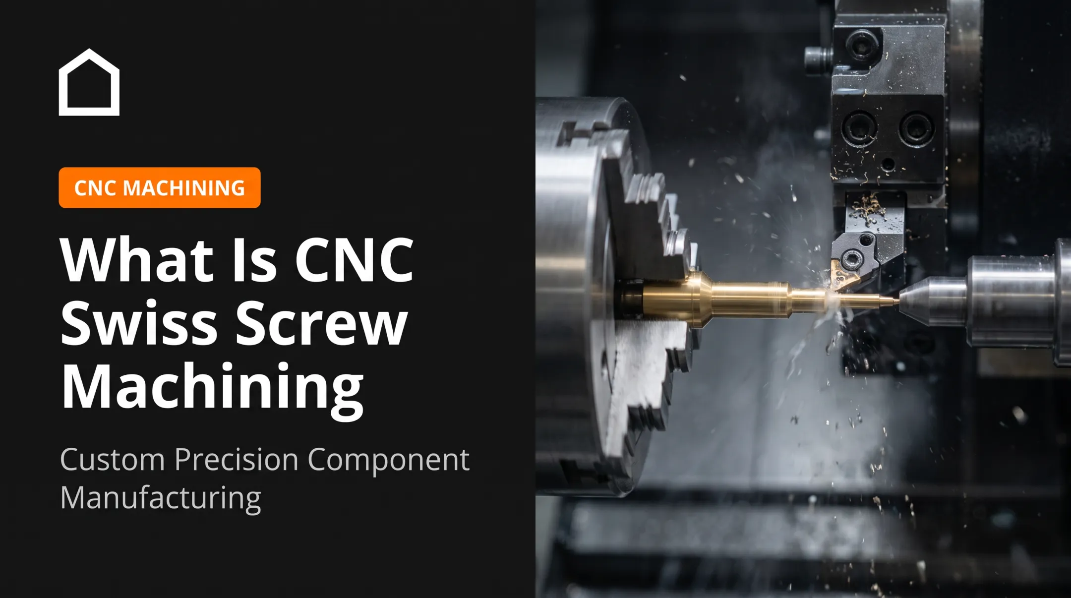
Once the cycle starts, the spindle rotates (or the workpiece spins, in turning) and sharp cutting inserts shear material away, forming chips. Multiple axes interpolate together, moving the tool along programmed vectors in coordinated X, Y, Z, and rotational motion.
Four variables control the outcome:
- Spindle speed (RPM) – how fast the tool or part rotates
- Feed rate (IPM) – how quickly the tool advances through material
- Depth of cut (DOC) – how much material is removed per pass
- Coolant application – manages heat and chip evacuation
Get these wrong and you'll see poor surface finish, shortened tool life, or excessive heat buildup. Sandvik Coromant's turning guidance recommends starting at a conservative feed to protect insert edges, then increasing it once chip control is confirmed.
Closed-Loop Control
Modern controllers don't just execute code blindly. Closed-loop feedback systems use linear scales and rotary encoders to compare actual axis position against the commanded position, continuously.
This monitoring extends further:
- Tool wear compensation adjusts offsets automatically as inserts wear
- Spindle load monitoring flags abnormal cutting forces
- Thermal expansion compensation corrects for heat-driven dimensional drift during long runs
These systems exist specifically to prevent tool breakage, gouging, and scrap during unattended or overnight production runs. Feedback alone, though, won't rescue a bad datum or a poorly proved-out program. It corrects drift, not fundamental setup errors.
Finished Part
The end result is a component holding specified dimensional tolerances and surface geometry. Some shops report holding +/-0.0002 to 0.0005 inch on suitable work. Tolerances tighter than +/-0.001 inch are noticeably harder to hold consistently, according to Modern Machine Shop.

Downstream steps often follow the cut itself:
- Deburring and bead blasting
- Heat treatment (before final hard turning or grinding, in many cases)
- Ultrasonic cleaning
- Coordinate measuring machine (CMM) inspection
That precision shows up on the floor. It decides whether parts mate correctly in high-stress tooling and industrial assemblies downstream.
Where CNC Machining Is Used
CNC machining delivers value across the full production lifecycle, from rapid prototyping and bridge tooling through full-scale production and tooling replacement. It's especially suited to environments with heavy mechanical loads, elevated temperatures, corrosive conditions, or cyclic fatigue.
Cross-industry applications include:
- Aerospace and defense: structural airframe components, landing gear details, and turbine housings requiring exotic alloys
- Industrial metal forming: replacement stamping press components, forging die inserts, cold header tooling details, and wear parts
- General manufacturing: custom machine parts, fixtures, and low-to-medium volume production runs where off-the-shelf parts don't fit
Manufacturers needing high-accuracy replacement tooling or custom production packages don't always have the in-house capacity to cover every job. That's where a Midwest-based tooling provider like Quality FORM Tools fits in. The company connects fastener manufacturers, forging shops, and OEM engineering teams with cold header tooling, forging dies, and precision machined components—from one-off prototypes to runs of 100,000 parts.

Conclusion
CNC machining works because it turns digital CAD models into physical, high-precision parts through a repeatable, closed-loop process. Once teams understand that sequence—from G-code generation through feedback-corrected cutting—part design decisions get sharper on both the engineering and procurement side.
Design for manufacturability, choose the right tool steel grade, and pick a machining partner who understands the tolerance stack-up before the first chip flies. That's the difference between a smooth production run and an expensive rework cycle.
Frequently Asked Questions
What does CNC machining do?
CNC machining automates the cutting, drilling, milling, and shaping of raw materials into finished parts. Computer-controlled tools follow G-code instructions to remove material with high repeatability and precision.
How much does it cost to have something CNC machined?
Costs vary widely based on material, part complexity, machine run time, and batch size. Typical shop rates range from $40 to $200+ per hour, depending on whether 3-axis or 5-axis equipment is required.
Why is CNC so expensive?
Upfront costs come from machinery investment, CAM programming, precision tooling, setup labor, and cycle time. Per-unit costs drop once you move into higher production volumes.
Where can I find online machining services?
Source machining through specialty tooling distributors, regional precision shops, or digital manufacturing networks. Match the supplier's specialty to your part's complexity rather than taking the first quote.
What are the two types of milling?
Climb milling rotates the cutter with the feed direction; conventional milling rotates against it. Sandvik Coromant generally prefers climb milling when the machine and fixture allow it, because conventional milling's initial rubbing shortens tool life.